2D to 3D Projection
The UniversalPlantViewer allows the creation of custom made image projections. 2D images are created with the AdapterForDocuments, while 360° panoramas are created with the AdapterForLaserScans.
Create a Projection
Start UPV and select your model.
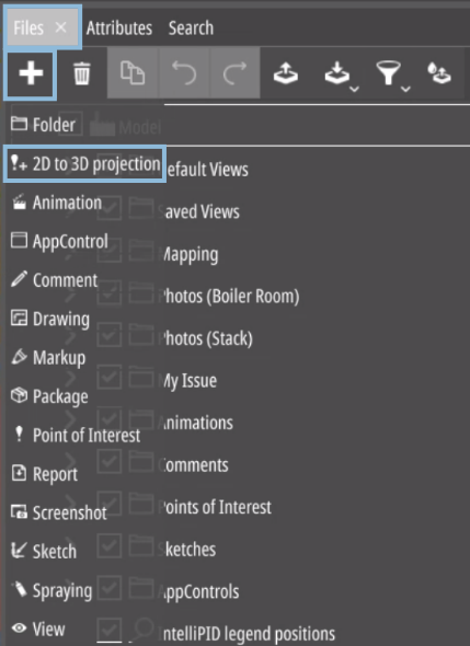
Create a projection by selecting “2D to 3D Projection” from the “Add” drop-down in the “Files” tab.
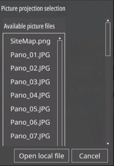
If you do not enter a name for the projection, the selected images name will be used.
- The selected image will be displayed on the right side.
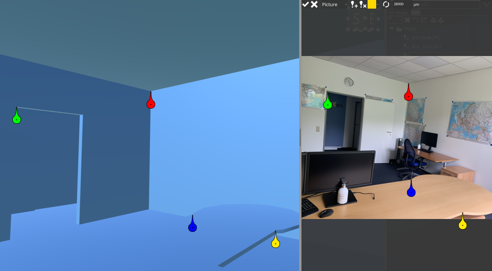
You can begin placing projection mapping markers on both the 2D image and in the 3D space of your model.
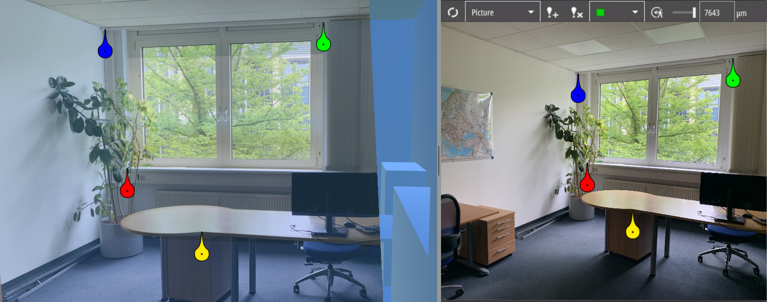
It’s recommended to position the camera in the 3D space as close as possible to where the image was taken.
The algorithm for mapping the image in the 3D space calculates multiple possible orientations of the projection sphere. However, it will ultimately choose the solution closest to the current camera position.
Mapping a Projection
Create a marker and drag it to its designated place in both the 2D and 3D space.
Add up to 4 markers for improved precision.
Move the camera towards where the picture might have been taken to ensure proper placement of the projection.
Recalculate the position.
If the image placement is not as desired, reposition the markers and recalculate until the images are properly placed.
|
|
“Adds a selection pin to the 2D mapping view and 3D view” This feature creates color-coded mapping markers that can be dragged and placed accurately in both spaces. You can place up to 4 markers, with a minimum of 3 usually required for decent mapping. |
|
|
“Removes a selection pin from the 2D mapping view and 3D view” |
|
|
“Changes the focused node” Selecting a marker centers both the 3D and 2D views. The marker’s color reflects its focus status, defaulting to red if not specified. |
|
|
“Refreshes the projection with the adjusted/pending measurement nodes” |
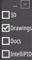
Picture, 360° Panorama, Orthogonal Drawing
Swap between “Picture, 360° Panorama and Orthogonal Drawing” by using the drop-down menu. Once a calculation has been done for the selected image, you can no longer change between the image types.
Picture
Pictures are standard 2D images projected into the 3D space. Adjust the “Focal length” as necessary, located to the right of the mapping buttons. Typically, the focal length is automatically retrieved from the image information.
After position calculation, the camera locks onto the projection sphere and operates similarly to the “360° panorama” mode.
|
|
Leave the projection sphere and use the camera as usual. |
|---|---|
|
|
Increases opacity of the projected image. |
360° Panorama
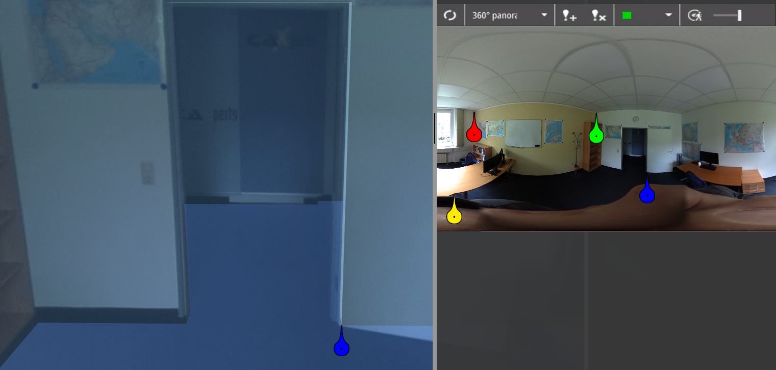
After calculating the position, the camera is locked to the projection sphere. Also, the following button and slider appear:
|
|
Leave the projectionsphere and use the camera as usual. |
|
|
Increases opacity of the projected image. |
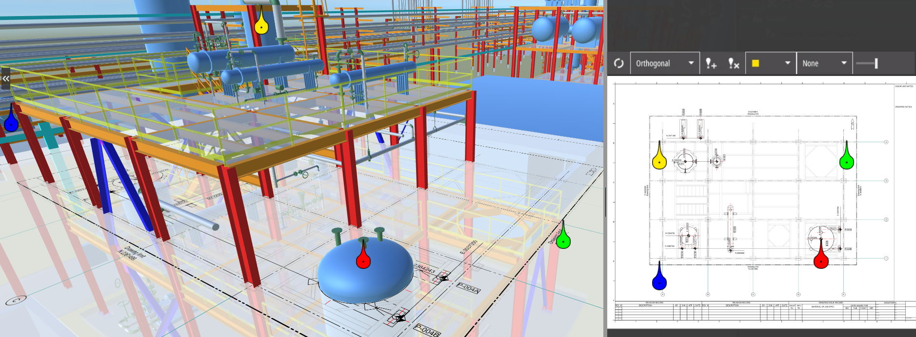
Orthogonal Drawing
To create a projection of an orthogonal drawing, select 2D from the breadcrumb menu and select the required drawing. It will be opened in a tab. While this tab is active, select 2D to 3D projection in the files tab of the right menu.
|
|
Select the plane the drawing should be in. |
|---|
None means the plane will be spanned between the first three markers. The others describe the axis the plane is a part of (e.g. X and Y axis in the image above).